
The edge and hole distance should be 1.0mm to the minimum. However, when the aperture is > 0.8 mm, the error needs to be ☐.1mm.Īpart from that, the shape and processing size should meet the drawing requirements. The acceptable line gap error is within ±5%.Īdditionally, the error between the part aperture and the designed aperture needs to be 4102 between ☐.05mm while the aperture is ≤0.8 mm. In addition to these, the notch must not exceed 1/5 line width. Apart from that, the wire width error should be within ±5%, and the bonding needs to be within ☐.01mm. Yes, the board should follow the thickness, perimeter, openings, slots, and cutouts. Therefore, you can find the most suitable one with a bit of research.Īlso, the board needs to meet the size demands mentioned in the design drawing. The manufacturers offer many options on the hole and drill sizes. When it comes to standard PCB drill sizes, the options are many. You can choose any method based on your convenience. If the size does not match, you will be left with no other choice except to make drills. However, you will have to find the right size component to get the best fit for existing drills. Yes, you will need this equipment to make drills effortlessly. Therefore, you will have to weigh the positives and negatives to find the most suitable one.įor example, if you use the drill size component, you can save on the CNC equipment. Both these methods will have some merits and downsides. You will also have the option to add the components that can fit the current holes of your PCB. In most conditions, you can consider making standard drills. But you will have to make sure that the new addition will not impact the functionality of other parts. In brief, you will need holes in your PCB to boost its functionality with some new additions. However, it will reduce the surface area. Here the PCB drills come in.Ī hole in the board might create a space for any component. The board needs to have a surface to support the attachments. However, they will require some space, and you will have to attach them to a circuit board. Electrical components play a determining role to offer the desired functionality. There are many components that you can add to a PCB design. But if you want to go a step further and make your PCB drill sizes, you can have a look at the following. However, if you do not have any specific requirements, you can consider a standard PCB drill size. The modern automated CNC devices are used to make any drill size on PCBs. Currently, PCBs are accessible with 10,000 drill holes or even more. 28mm which are both 0.0110 inches in diameter, the 13 and the 4.7mm which are both 0.1850 inches in diameter, the 4.8mm and the 12 which are both 0.1890 inches in diameter, and the 1/4 inch and letter E bits which are both 0.250 inches in diameter.Īll of the drill bits are listed below with their decimal equivalents.What are the standard PCB drill sizes? Can one find a customized solution based on the unique requirements? Yes, both standard PCB drill sizes and customized solutions are available. 22mm which are both 0.0087 inches in diameter, the 85 and the. All of these drill bits are different in size except for the 90 and. The metric sizes are dispersed throughout. Where the number 1 drill bit leaves off the letter A (smallest) begins and continues through the letter Z (largest). The numbers range from 107 (smallest) to 1 (largest). The fractions range from 1/64 inch to 32/64 inch. You will see drill bits with a fraction, number, letter or metric number stamped on their shank indicating their size.

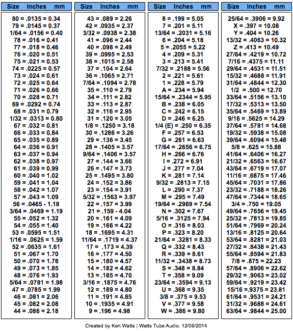
Drill bits from zero to one half inch are sized in four ways fractions, wire gauge numbers, letters, and metric in millimeters.


 0 kommentar(er)
